A dedicated CAE solution for the lost-wax process, built around multi-layer ceramic shells, radiation-dominated cooling, and fine feature resolution. Validate gating and thermal cycles before the first wax pattern is built.
Automatic generation of multi-layer ceramic shells around thin-walled part geometries
Calculate flow, solidification, shrinkage, stress, warping, and microstructure
Supports all common investment casting alloys, from aluminium to nickel superalloys
.svg)
Reduce trial castings by validating the casting tree, shell thickness, gating system, pouring temperature, and cooling conditions before production.
.svg)
Predict incomplete filling, cold shuts, shrinkage cavities, macro and microporosity, hot spots, residual stresses, cracks, and warping in complex precision castings.

Adjust shell layers, insulation, gate locations, feeder design, mold preheat, transfer time, and cooling strategy to improve yield and repeatability.

The simulation strategy for investment casting in PoligonSoft is built on the principle that casting defects are influenced by the entire thermal history of the process, not just the pouring phase.
PoligonSoft’s solvers enable a seamless, continuous simulation of the complete investment casting cycle. This includes modeling the preheating of the ceramic shell, its inevitable heat loss during transfer from the furnace to the pouring station, and the hydrodynamics of filling the hot mold. Furthermore, the software accurately tracks the directional solidification and subsequent cooling stages, taking into account heat radiation and the use of thermal insulation wraps up to the final knockout.
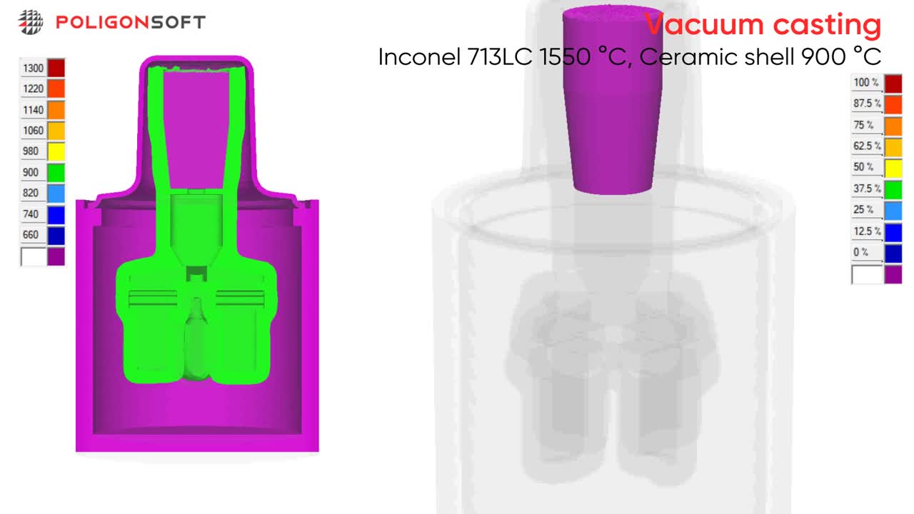
PoligonSoft solves complex radiative heat-transfer problems, accounting for re-radiation and surface shading. This capability models thermal behavior in processes where radiation dominates the heat-transfer mechanism. The software computes view factors and surface-to-surface exchanges to determine temperature distribution throughout the casting process. The radiation solver considers emissivity variations, geometric configurations, and multiple reflections between surfaces.
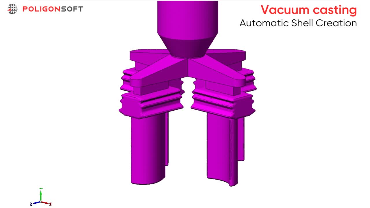
The Shell Creation algorithm generates a finite element shell mesh directly from the wax pattern surface at a user defined thickness, without prior CAD construction. The shell may represent covers, refractory coatings, or insulating layers, each with its material properties and thermal characteristics. Multiple layers with different thicknesses and properties can be created to reflect the ceramic shell build up used in investment casting. The mesh is saved in a format ready for filling and thermal analyses, removing the need for manual mesh preparation.
Shell mold preheating
Mold transfer to pouring station
Placement in support sand bed
Gravity pouring
Solidification
Ambient air cooling
Shell knockout
Gating and riser cutting
Load STEP/IGES, auto-heal geometry, and mesh the part, gating system, and ceramic shell domain.
Select alloy grade and thermophysical properties. Specify ceramic shell layers, thicknesses, emissivity, and the interfacial heat transfer model.
Enter melt and shell preheat temperatures, mold transfer time (heat loss), pouring schedule, cooling environment, and analysis times.
Launch Euler Flow, Fourier Solidification, and Hooke Stress solvers in a single run on up to 24‑core multi‑threaded CPUs.
Review temperature and velocity fields, solidification dynamics, free-surface evolution, hot-spot and shrinkage-risk maps, and residual-stress fields.
Modify the design and process parameters, then re-run fast iterative simulations until targets are met.

An example of using PoligonSoft to predict shrinkage porosity in a complex DS45 steel investment casting.

Initial castings were examined using fluorescent penetrant inspection and radiography. Both macro and micro porosity were detected, with individual pores larger than 0.2 mm.
Due to the blade geometry, hot spots form at the blade-to-platform transition zones, and the blade’s central region shows a tendency to develop shrinkage defects.

Material: Nickel superalloy CHS70
Mold: Ceramic shell with thermal insulation
Mold Preheat: 1050 °C
Equipment: UPPF-3M
Pouring temperature: 1500 °C
Vacuum exposure: 180 s
Cooling: Air
PoligonSoft solves the coupled heat and mass transfer in the solidifying casting using the finite element method (FEM).
To run the simulation, a mesh model of the computational domain is required. In this case, the domain consists of the metal, the ceramic shell, and the thermal insulation.
The Shell Generator allows the automatic creation, without prior manual constructions, of a mesh model of the ceramic shell and the insulation layer with specified thicknesses, based on the part’s 3D model.

Shell generation steps

Thermal
insulation
Ceramic shell
Ceramic fiber insulation
Refractory
brick
Radiation shield
Vacuum furnace computational domain
A process model was formulated with the following calculation sequence:
Cooling of the empty mold from its extraction from the preheating furnace up to metal pouring.
Solidification simulation from mold filling to air ingress.
Solidification simulation from air ingress to complete solidification in open air.

Heating + Transfer + Vacuuming
Pouring + Vacuum Holding + Cooling

Mold temperature field at the start of pouring.

Casting temperature and porosity at the moment of air ingress.

Predicted porosity after cooling compared with metallographic sections of the real part.
To eliminate defects, solidification simulation in PoligonSoft was performed for several feeder sizes.
The casting is considered acceptable if the simulation predicts no porosity in the previously identified critical sections.
Increasing the feeder mass or changing only the insulation scheme of the casting block did not remove porosity in the blade.
The design was updated to add an additional vertical feeder in the problematic zone.


Practical workshops and webinars cover casting techniques, offering theoretical and applied sessions to master simulations.

Complete reference covering software interface, simulation settings, analysis tools, and practical recommendations.

Peer‑reviewed document outlines algorithms, validation data, and industrial cases supporting simulation accuracy and reliability.


.svg)
.svg)
.svg)

.svg)