After installation, an icon  will appear on the Windows desktop, which launches POLIGONSOFT shell (see the figure below).
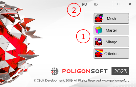
The window has a panel for system modules launching (1) and a settings panel (2). The following commands are available on the settings panel:
 change interface language;
 open POLIGONSOFT documentation.
POLIGONSOFT modules are launched by buttons located on the panel (1) in the right part of the shell window. You can open several instances of one module, their number is regulated by the license.
The model created in the CAD system is converted into a finite element model in the mesh generator, launched by the Mesh button (see the figure below).
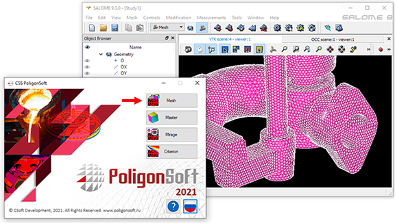
The module imports a model in STEP format, analyzes geometry, finds contact surfaces between bodies and generates volumetric tetrahedral coincident meshes. The resulting mesh model is exported in MED format.
The mesh model in MED format is imported into the Master preprocessor, which is launched by pressing the Master button from the POLIGONSOFT shell (see figure below). In addition to MED files, meshes of other formats can be loaded into the module, so when the module starts, the model does not open automatically. Files written in the POLIGONSOFT format (have the g3d extension and an  icon) can be opened directly from Windows Explorer or another file manager.
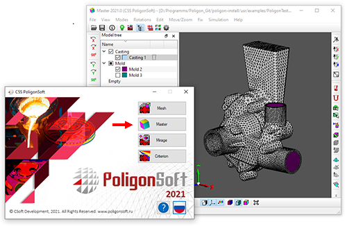
In the Master module, the model is prepared for calculation and the solvers are launched. Depending on the task being solved, the Master can use other modules that are part of the system, for example, the Tracing module or the database editors. When the calculation is started, the Master generates a command .bat file, in which the sequence of work of the Euler, Fourier, Hooke and other solvers is determined. Solvers do not have interfaces and work independently according to a given scenario. For more information on working with the module, see the chapter Chapter 5. Data Preparation.
The results can be viewed (including during the calculation), in the postprocessor Mirage, which is launched by pressing the Mirage button from the POLIGONSOFT shell (see figure below). After starting, load the file of the required calculation fields. These files can be opened directly from Windows Explorer or another file manager.
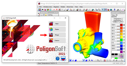
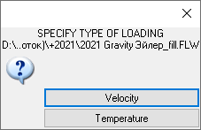
When loading the mold filling calculation results (.flw files) from the file manager, a request appears, specifying which calculation fields should be loaded (see the figure below). After pressing the Velocity button, the field of melt velocities will be loaded into the Mirage module. If the Temperature button is selected, the temperature fields will be loaded.
Information about values changing of the calculated fields in mesh nodes can be viewed as curves in the Mirage-L module, which is launched from the Master postprocessor. For more information on working with the module, see the chapter Chapter 7. Viewing Results.
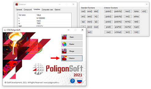
Possibilities of additional analysis of calculation results using criteria are provided by the Criterion module, which is launched by pressing the Criterion button from the POLIGONSOFT shell (see the figure below). For more details on working with the module, see the chapter Chapter 8. Results Analysis.
Closing the POLIGONSOFT shell and restarting it are not associated with previously launched modules and do not lead to their closing or stopping.


.svg)
.svg)
.svg)

.svg)